
PowerBusbar PF
PowerBusbar PF
The game changer for thermal management
Ideal for reinforcing current paths, heat dissipation and the prevention of hotspots in the overall system
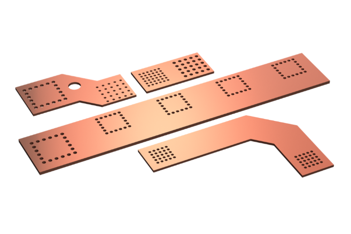
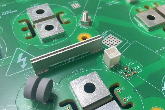
With the PowerBusbar PF busbars, you receive an innovative and cost‑effective solution for reliably distributing high currents on your printed circuit board while optimizing thermal management. The copper busbars are vertically press‑fit into the PCB using solid press‑in technology, making them ideal for applications with limited installation space. The modular design and different dimensions available, allows for flexible use across a wide range of applications. Standard lengths from 19 to 59 mm are available, with a material thickness of 1.2 mm.
Why you should integrate PowerBusbar PF into your PCB layout
- You have a current path and want to increase its current‑carrying capacity
- You have one or more thermal hotspots in your system and want to optimize thermal management
- Due to your PCB layout, you need a current bridge to connect two components (3D layout)


Further information
Application possibilities
- Reinforcement of the high‑current path
- Implementation of a high‑current bridge
- Use as a heat sink to prevent hotspots / optimize thermal management
From sample to market
Samples are available even in small quantities. Just tell us what you need!
Packaging
Bulk
Application example
Use as heat sink for hotspot prevention
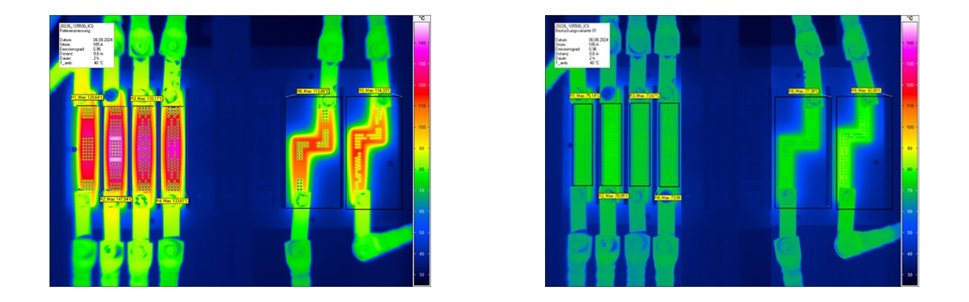
Thermographic images clearly illustrate the advantages of using PowerBusbar PF. While the image on the left shows the condition without vertical busbars, the image on the right shows the PowerBusbar PF installed. Their use achieves a temperature reduction of up to 53.5 kelvin. This clearly demonstrates the heat-dissipating effect of the vertical busbars as heat sinks and their contribution to optimizing thermal management.
The measurements were carried out under identical conditions: an ambient temperature of 40 °C and a constant current flow of 185 A.
More application examples
Reinforcement of high‑current paths
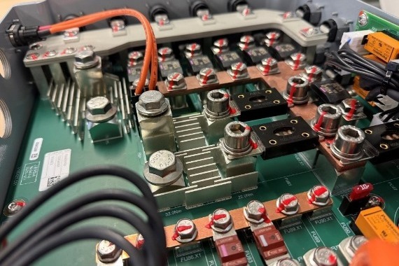
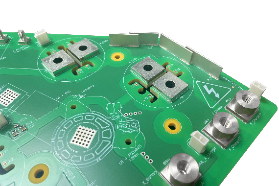
Despite limited space on the printed circuit board, high‑current paths can be implemented. Since the PowerBusbar PF is press‑fitted vertically, the required space on the PCB is very small. Different lengths of the PowerBusbar PF can be connected in series to form the high‑current path.
Implementation of high‑current bridges
Due to the required crossing of the high‑current paths on the PCB traces, PowerBusbar PF busbars are placed on the PCB. The busbars are used as a bridge to establish a high‑current connection between the two components.
Benefits with PowerBusbar PF
- Efficient heat dissipation: The PowerBusbar PF acts as a heat sink. Thanks to its high thermal conductivity, it reliably transfers the generated heat out of the system, thereby reducing hot spots – for increased reliability even at high currents.
- Targeted increase in current-carrying capacity: By using PowerBusbar PF, current paths on the PCB can be selectively reinforced, making them ideal conductors for efficient, low-loss current transmission.
- Space-saving / suitable for limited installation space: Since the PowerBusbar PF is press‑fitted vertically into the PCB, a 3D layout is created that provides additional design freedom even when space on the printed circuit board is limited.
- Bridging of PCB traces: If suitable PCB traces for high currents are not available, PowerBusbar PF busbars can be used specifically as high‑current bridges. They are placed directly on the PCB and reliably connect two components – ideal for compensating for missing copper structures and creating stable high‑current paths.
- Cost advantages through the use of standard PCBs: The use of PowerBusbar PF eliminates the need for special thick‑copper PCBs or PCBs with copper inlays, as increased current requirements are handled by the busbar. This allows cost‑efficient standard PCBs to be used without compromising performance or reliability.
- Modular concept for flexible designs: The available standard lengths can be freely combined, enabling a modular and application‑specific implementation on the PCB.
- Easy processing thanks to solid press‑fit technology: The PowerBusbar PF busbars are based on Würth Elektronik ICS’s proven PF technology and can be press‑fitted quickly, reliably, and without thermal stress into the PCB.
- REACH and RoHS compliant

Processing options for PowerBusbar PF


MPFT (Massive Press‑Fit Technology)
In massive press‑fit technology, solid pins are pressed into a plated‑through hole of the printed circuit board. Due to their excellent mechanical and electrical properties, press‑fit Powerelements are particularly suitable for use under demanding conditions such as high temperature fluctuations or vibrations. During the press‑fit process, a high‑performance, gas‑tight cold‑welded connection is formed with a contact resistance of only a few micro‑ohms (μΩ). This ensures very high current‑carrying capacity through low‑resistance contact points.
PCB design requirements
The printed circuit boards must be manufactured in accordance with IPC‑A‑600 in the currently valid edition. For massive press‑fit technology, the PCBs must additionally comply with the Würth Elektronik ICS press‑fit specification. Particular attention must be paid to drill diameters and copper thicknesses.
Further information
Current carrying capacity
The current‑carrying capacity must be considered in the context of the overall system. It depends, among other factors, on the PCB layout, the Powerelements, the design of the busbar, and the connection of external supply lines. Our measurements have shown that the limiting factor is usually found in the PCB layout or in the connection of external supply lines (transition resistance of the press‑fit zone: 100–200 μΩ).
Qualification
PowerBusbar PF have successfully passed the vibration test and the mechanical shock test.
- Vibration test according to IEC 60068-2-64 Random.
- Mechanical shock test according to IEC 60068-2-27.